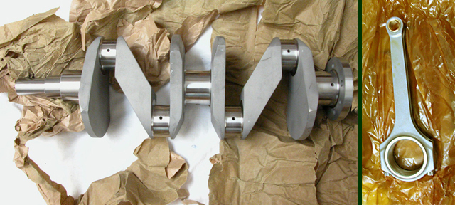
THE PHOENIX CRANKSHAFT AND CARRILLO TYPE ROD
Lovely bits of machinery.
|
1.) The Phoenix crank weighs 32 pounds 14 oz. The counter balances, opposite the rod journals, add considerably to the weight over that of the original non-counterbalanced crank. My original crank (having been turned to about -.020) weighs 22 pounds 14 oz. |
Disclaimer:
The information here describes my own experiences with the Phoenix Crankshaft and Rods and is not intended to be used as a 'how to' guide for installing their products. Anyone following these procedures does so at his own risk.
This is Page ONE of THREE. See the links at the BOTTOM of the page to continue the Phoenix saga.
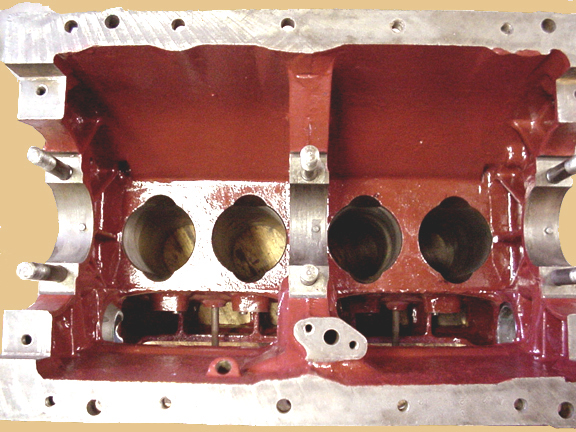
THE MPJG ENGINE BLOCK
Before the main bearings were align bored I was able to determine that there would need to be about .060 ground away from the front side of the oil pick-up on the block to allow the rear counter balance of #2 big end journal on the crankshaft to rotate freely.
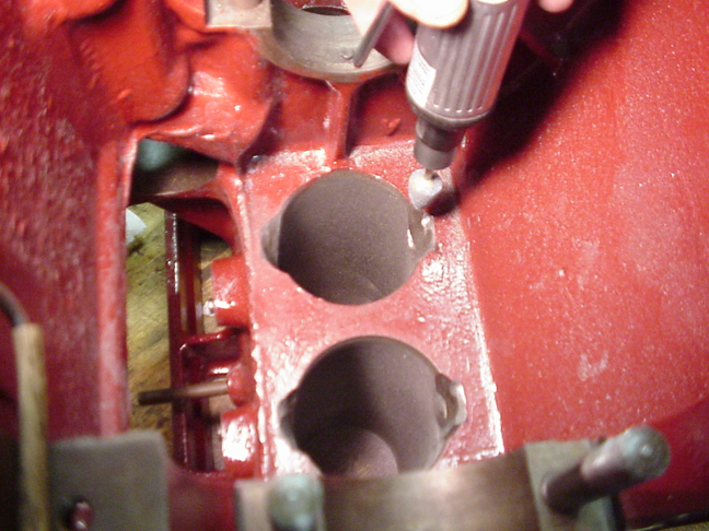
DETERMINING WHERE AND HOW MUCH OF THE OIL PICK-UP TO GRIND AWAY
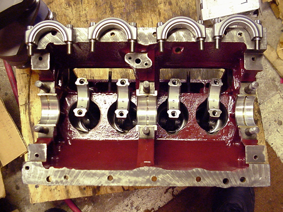
With the engine upside down cardboard strips were cut to lay in the block where the upper main bearings will go. These will protect the journals of the crank and also give me a rough idea where crank will ride. Also for protection I cut short pieces of PVC water pipe to slip over each of the main bearing studs (seen in one of the photos below). I carefully set the crank into these cardboard 'bearings' then rotated it keeping the center main journal as close to being centered in it's saddle as possible. As it rotates the rear counter balance of #2 brushes against the casting of the oil pick-up.
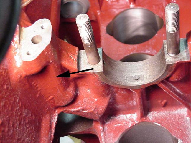
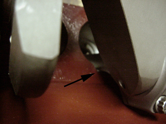
AREA WHERE THE OIL PICK-UP IS RELIEVED
It's pretty thick here and grinding will take place along the area where arrow (above) is pointing. With the counterbalance against oil pick-up I measured the space between the center main bearing seat in the block and the forward thrust area of the crank. The difference between that and the rear measurement plus about .060 is the amount that will need to be removed from the casting at the oil pick-up. The rotation of the counter balance will also show where (up and down on the oil pick-up) grinding will be required.
NEXT STEP: OFF TO THE MACHINE SHOP FOR ALIGN BORING
Once the main bearings had been align bored I removed the bearing caps, smeared a light coat of Lubriplate 105 on the caps and journals of the crank and placed it into the bearings. I rotated it to make sure I had the clearance I wanted between #2 rear counterbalance and the oil pick-up passage. And then cleaned off the journals, put in Plastigage and torqued the mains to 50 lb./sq/in. Pleased with the 0.0015 in. clearance in each journal, I cleaned off the Plastigage, re-lubed, tightened and then rotated the crankshaft through a couple of revolutions to make sure it moved freely and had no binds.
The crank will have to be removed so that the pistons with rods attached can be placed into their respective cylinders.
A Note About Rod and Piston Installation When Using Phoenix Cranks:
The pistons and rods must be installed from the bottom but unlike the original set-up they will not pass by the counter balances of the Phoenix crank and so must be installed before the crankshaft goes in. Therefore once installed they cannot be removed out the bottom of the engine as was the custom using the old style crankshaft, pistons and rods.
Damage to a piston, or a simple change of rings for instance, in the future will necessitate removing the crankshaft!
(And to remove the crankshaft we must first remove the engine!!!)
The big-end bearings of the Carrillo type rod, however, may be replaced or checked from beneath without having to remove rods or crank.
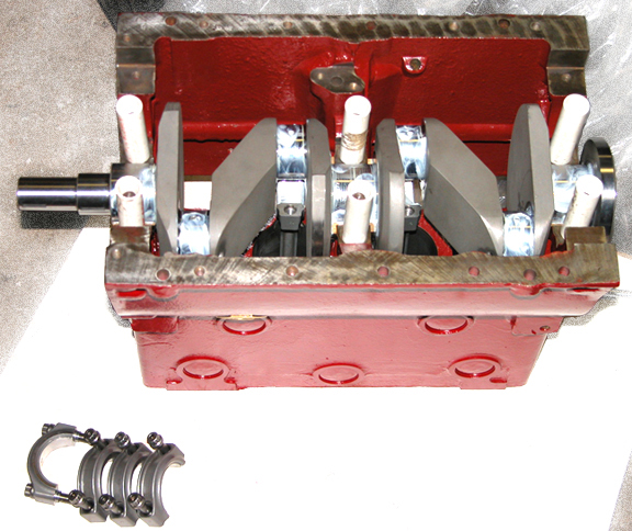
I oiled the pistons and cylinders (but didn't put rings on the pistons) and placed them into the block. I lubed all my bearings lightly and replace the main bearing caps bringing the rods up to mate with their journals and replace their caps. There is no need to torque the fasteners yet, snug will do. All I'm doing here is determining how much to grind off those cones so the new rods will have adequate clearance. The photo above shows the PVC pipe sections I used over the main bearing studs to protect the journals when taking the crank in and out.
With the mains and rods snugged down I mark the locations for more grinding.
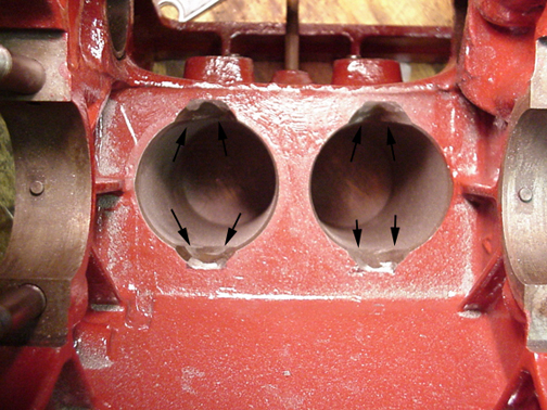
MARKING THE BLOCK
I watch the rods carefully as they make their way down (and up) the cylinders. On my installation I found that there was about .001 interference between the bottom of the cylinder walls on the Off Side (right side of the engine) but none on the other. Grinding out the cones is necessary because the Phoenix rods are wider and thicker and taller at the shoulder than the original.
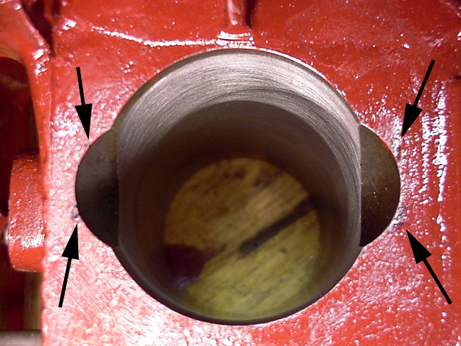
My marks can be seen on each side at the bottom of the cylinder beside where the rod comes near or touches the conical area in the block. This wasn't precise but just a good guide for grinding out and sort of squaring off the original cones in the cylinder walls.
GRINDING THE NOTCHES
I removed enough from theses places to allow at least .060 clearance, on each side, when the rods swing through their cycle.
Because the Phoenix rods are taller at the shoulder than the original rods I also had to go deeper into the narrow parts of the cone and square them up as well. One good thing about all this grinding is that it did not render the block unusable if I decide to go back to my original crankshaft.
Deciding just How Much to remove was scary. Too much and I could enter the water jacket. Too little and if, in the future, I spin a rod bearing the rod might end up flailing itself against the cylinder wall damaging the rod and creating more havoc than just a spun bearing!
Grinding and checking and grinding again is a time intensive process requiring total cleaning to remove any grit or filings each time you put the pistons, rods and crank back into the block. I used hot soapy water and pressure washed the block each time between clearance checks. Then dried it with compressed air, relubed the cylinders and replaced the main bearing shells to have another go at it. I believe (based only on dealing with my block) there's enough meat at the bottom of these engines which can safely be removed if one will take plenty of time and make several checks to see how the fit is coming along.
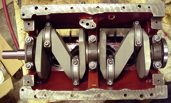
ALL BUTTONED UP AND READY FOR THE END BRIDGES
Once the grinding was all done and the block truly cleaned, the pistons, now with rings in place, could then be installed. The pistons and rings were dipped into Rotella-T* diesel oil. The cylinder walls were drenched as well and then the pistons were inserted into the bottom of the cylinders. I replaced the crank and brought the rods up and mated them with the crankshaft. A liberal coating of Lubriplate 105 was used on all surfaces of the main and rod journals. Next, using new nuts, I torqued my main bearings to 45 lb. I Plastigaged the rod journals and torqued the bolts to Phoenix's recommended 60 lb and used Locktite on all the (cleaned) threads. Then I rotated the crankshaft one more time just to make sure everything turned freely.
Now the reassembly can begin in ernest.
Well, almost. Problems with the Phoenix Crankshaft seemed to multiply.
The first I was faced with was a discrepancy with the Woodruff key sizes.
Follow Phoenix Two and Phoenix Three to read more.
| Phoenix Two | Phoenix Three |
About That Oil
(* The Shell Rotella-T 30 wt. I used was purchased in 2006, prior to reports that in Jan. '07 their diesel oil would be reduced in ZDDP.)
RUNNING IN
This seems out of place but since bringing up oil I'll mention that Rotella-T 30 wt. was used for break-in oil and changed after approx. 40 minutes and again at 100 miles. Also included at each of those oil and filter changes was a 16 oz. bottle of GM's EOS. And as mentioned above I used Lubriplate 105 on all the bearings and Clevite Cam Lube on the cam and lifters during engine assembly.
This is NOT an endorsement but simply a statement of the lubricants I used.
Contents of this Web Site are copyright © 2020
B Davis.