Questions are often raised as to what was and was not original to our cars. It's well known that the TA was assembled with as many current-day Morris/Wolseley parts as could be in order to save money and 'unify' as many systems as possible throughout the Nuffield line of automobiles. Original in this sense is meant to be what was on a car when it left the Works. This can get a little fuzzy because of all the modifications made to body, engine and gearbox throughout production and the best way to answer the question is to start with the production date of a car. Production dates can be found by entering the chassis number of the car in question at the MG T-Register's website here. It is hoped that you’ll find answers for some of your questions on originality below. There are also questions here which are not answered !
David Irwin's 1936 TA0655 There are few examples of original TAs that survive today and TA0655 is one of those rare cars. While it is not without a few owner-mods, it is an exceptional example of an early car (the 404th TA built), and we are fortunate to have a glimpse at some of its details. Information on how David came upon this true barn-find my be read at the MG T-ABC.org website here. A few Stats To Begin With
The were two versions of TA Roadster bodies; an Early (B269) and a Late (B270).
Below are details from original and surviving cars.
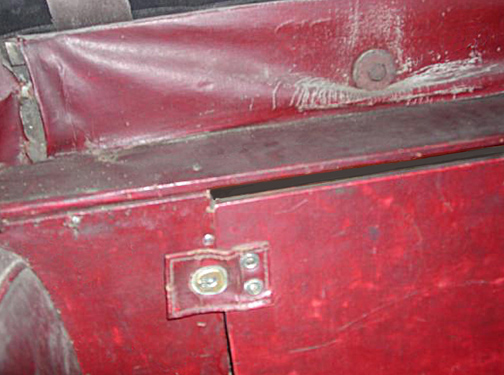
Side Curtain Door Latching Strap on TA0655 These straps were made from the same Rexine as used throughout the interior. And were found on both early and late bodies. They were attached to the door with screws as shown.
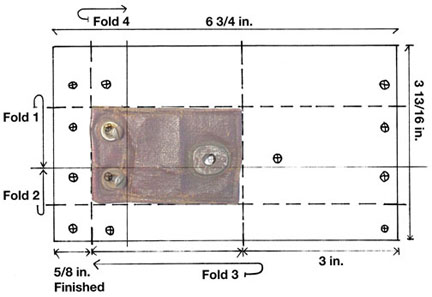
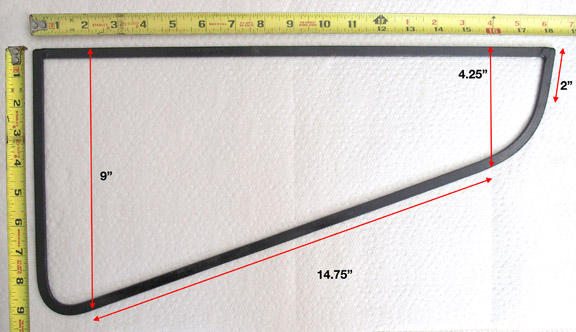
Here's how the strap is constructed. The folds are represented by the dotted lines. Note that the first two folds don't meet in the center. This allows the hole for the Lift-the-Dot to be on the wider side of the Rexine. After these two folds the 3 in. side is folded back onto itself leaving the small flap to fold over it making clean edges all around. The difference between the 6 3/4 in. on one side and 6 5/8 in. on the other is the allowance for the material making the folds. The fourth fold finishes up with a 5/8 inch flap in the back under where the screws attach it to the door.
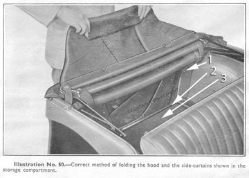
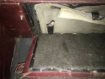
It is possible that earlier cars (B269 bodied) may have had slightly smaller straps with a finished size of 2 7/8 in. by 1 11/16 in. The measurements in the diagram were taken from TA2190, a late car. The photo below from the Owners Manual shows the side curtain door (opened) over the shelf above the differential.
Key to Photo above
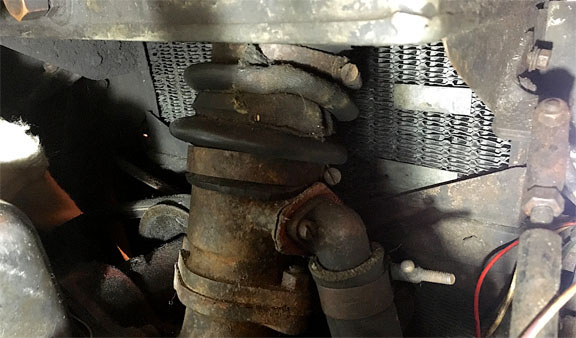
#3, from the Owner's Manual above, points to the black felt protective covering for the curtains. (same as the felt inside the side curtain compartment) It is held in place on the door with tacks through the rexine. Tacks were possible inside the box and otherwise glued to the four sides. LIFT STRAP FOR DIFF SHELF? The photo below shows what appears to be a strap with which to lift the shelf over the differential. Getting to the batteries is essential in the TA and a strap such as this would aid in lifting that piece of plywood. TA2190 had the ends of what may have been this rexine lift strap tacked to the under side. Anyone else have the same?
HOOD AND SIDE CURTAINS
Alumininum Moulding ?? Sewn into the lower portion of the front curtains was a metal ’stiffener’ which aided in lifting the flap for giving turn signals or, as some do, opening the outside door latch. It also kept that flap more rigid at speed than it would have been with canvas alone.
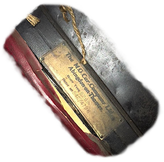
Side Curtain Iron Stiffener Body Number Plate For TA0655
The body number is different from the chassis number and because they were built at a different facility and then delivered to the Works in batches, not all were placed on chassis in numerical sequence. As stated above, the number is also stamped into the wood near the center of the uppermost cross-piece above the toe board. With a bit of contortion and a flashlight/torch it should be visible. Air Cushions For The Seats
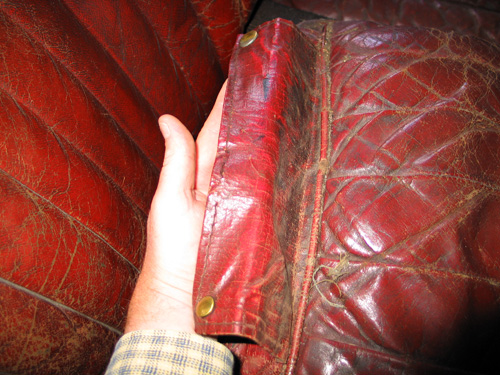
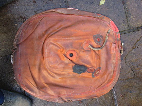
Originally the TA had an inflatable cushion (an 'air bladder') inside the seats and underneath the Dunlopillow. It was accessed for service or replacement by unsnapping the flap at the rear as shown in this photo by David Irwin. Using the tyre pump in the tool kit one could adjust the firmness to one's own preference. Most of these air cushions are now long gone, replaced with foam rubber or some other support substances.
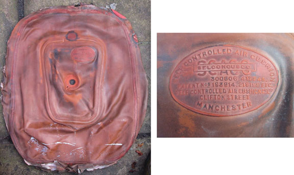
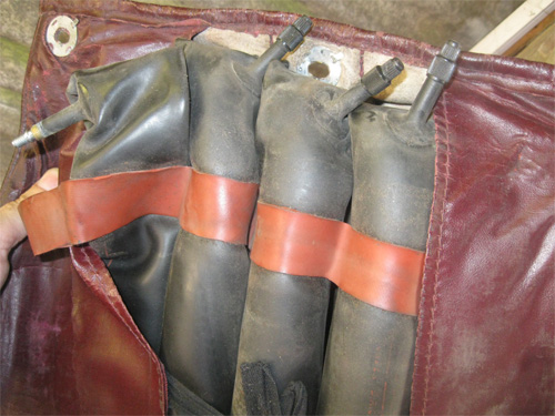
The photos above are the top-side of what’s left of one of the inflatable cushions from Mike Henning's TA1722. They were still in use until the car was taken off the road about 1968. It certainly has the look of something that could have been original. The company who made it, Self Controlled Air Cushion Co. Ltd. of Manchester, were advertising their air cushions in trade magazines in 1923 so there’s definitely the possibility that they were a supplier to the M.G. Car Company. They also manufactured aftermarket air cushions for various automobiles and motorbikes. The one pictured above has two air compartments that were inflated separately through the valves as shown in the photo below.
To clarify this business about 'air bladders' and cushions; I should point out that The Service Parts List refers to the Dunlopillows (and they are 'handed' O/S and N/S) as "Seat Cushions" - Part No.s B269/131 and B269/132. Morgan cars also used inflatable cushions well into the 1960s and a modern version is available through Melvin Rutter Limited, UK. When I inquired through their website about the size I was told they were 46cm by 39.5cm but they could not confirm an inflated height/thickness. However I believe they should fit inside the TA seat. Has anyone tried these in a TA yet?
Until the photos of Mike Henning's air cushion came to light I thought perhaps the inner tube design (above) might also have been used in the seats of the TA as well. Gary Perry sent this photo of the original air bladders used in the back-rest of his early M.G. SA. But somehow, in my humble opinion, they don't lend themselves to the job like the "Self Controlled Air Cushion" does.
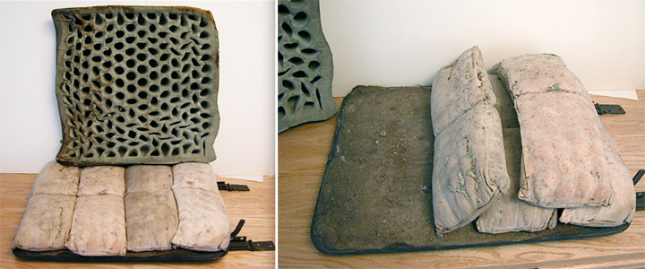
I mentioned the Dunlopillow earlier and show here the bottom side of one of these rubber cushions. A pair of these are in the seats of TA2190. As best I remember it is about 4 inches thick and solid on the top side. The car came to me with the original leather but without the air bags mentioned in the Service Parts List. In their place were these 'packets' stuffed with compressed cotton resembling parts of an old life jacket ..and not very soft as seating! Disregarding them, note the plywood seat bottom on the right. It has a covering of burlap with a nap woven into it which must have helped protect the air bag resting on it. On renewing the seat leathers and lacking air bags, I used high density foam where those packets had been and topped that with the original Dunlopillows. TAs on the production line
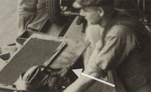
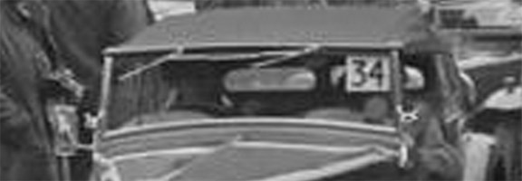
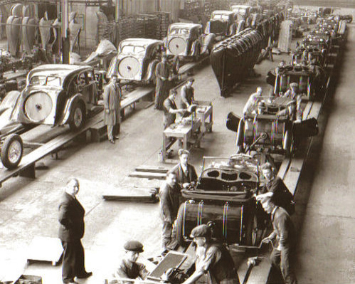
Wouldn't we love to talk with these gentlemen?! These would be the early cars (B269 bodies) with the wider fuel tanks. The two men at the bottom of the photo appear to have a diff shelf/side curtain box door there over the engine. While the man on the right above them with the hand crank wrench appears to be tightening the spare wheel bracket. The gentlemen above him may be installing the hood (canvas top). The car above them has received its rear wings. The dashboard with instruments doesn't appear till 5 or 6 cars up the line. And all the while the beautiful SAs are being assembled on the left. Did the men work one day on the TA and the next on the SA? Or was there a different group of men who assembled the SA? The Dash Wood
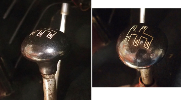
Note the vertical seam in the wood above the instrument panel. The Shift Knob
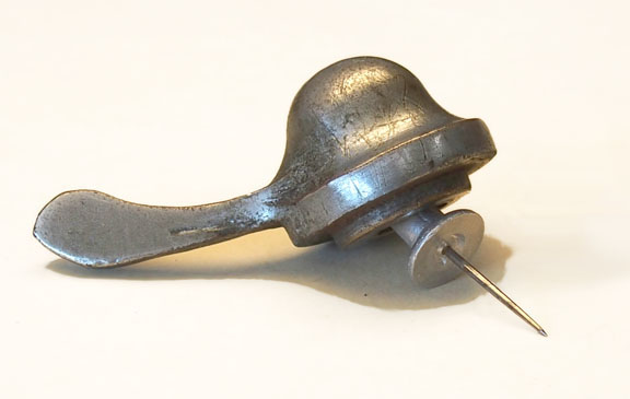
The gear shift knobs were a mushroom-shape and unique to the TA. Enot & Tecalemit Grease Nipples
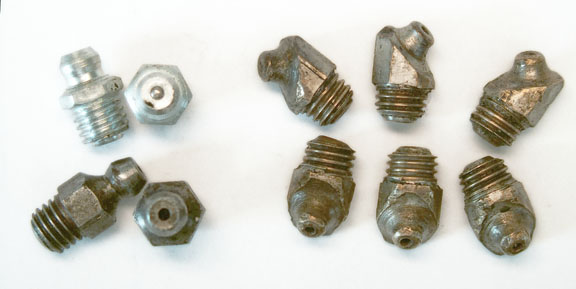
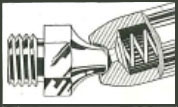
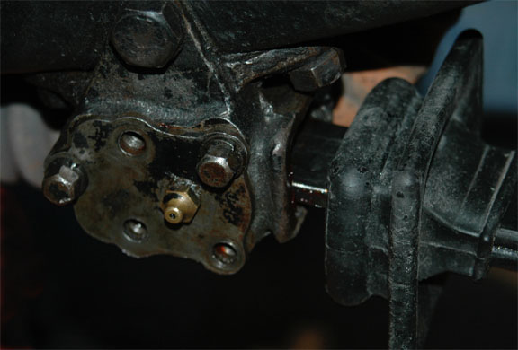
Above, Right, are 6 brass 45 degree Enot grease fittings. These were used at various places on our cars through chassis No. TA2517. Notice the 'hole' in both Tecalemit and Enot fittings where the oil/grease enters, and now the ball showing in the head of the Zerk fitting. These older oilers have a short passageway before the lubrication passes the ball and spring and because there's a chance debris can enter they're not quite as clean the modern Zerk fittings. Another difference between these Enot and Tecalemit fittings is the method of applying the gun. With Tecalemit (and Zerk) the 'knob' is captured inside the end of the gun-tip whereas the gun used with Enot fittings (with different end of course) must be pushed hard against the fitting before forcing in oil or grease, as below.
Straight Enot Fitting - Rear of Front Road Spring The cover on this trunnion box is being replaced after new trunnions were installed. There was no gasket or sealant found between the cover and housing. Any excess oil forced inside will easily find its way out and into the rubber dust cover (yet to be fitted over the lip around the box). If pure originality is the goal for a car prior to TA2518 then the Enot fittings are correct. For the rest, it is doubted that a Concours Judge will note the difference between the Tecalemit and Zerk fitting. Early and Late MPJG Fume Pipes
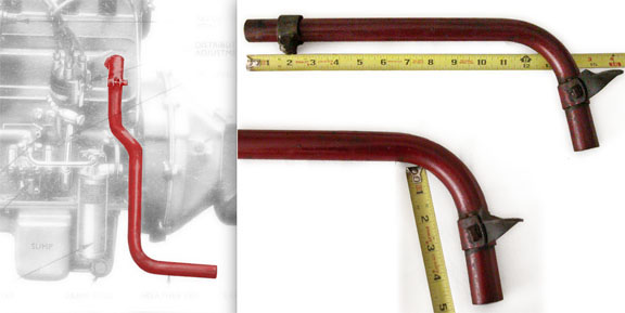
Although the Tecalemit oil filter is somewhat grayed out, you can see how the Fume Pipe bends around it and the plumbing on engines through MPJG 1513. Oil leaving the Tecalemit filter housing on later blocks (MPJG 1514 and beyond) flowed directly into the oil gallery and a straight-down fume pipe was used. Earthing / Ground Strap
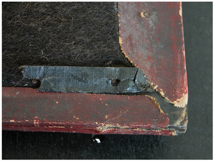
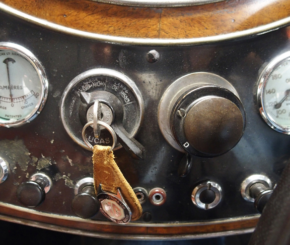
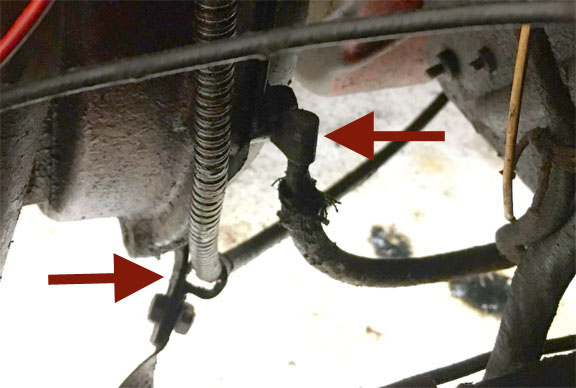
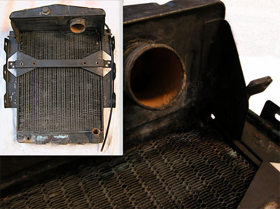
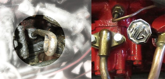
Some later TAs had the Earth (Ground) cable attached to the chassis at the 3-way brake fitting and to the rear of the transmission but the strap on TA0655 (right arrow) grounds the electrical circuit to the flywheel housing. Were all early cars Earthed there? Another item noticed was the location of the P-Clip (left arrow) through which the speedometer cable passes toward the transmission. It is attached to the bracket which stabilizes the lower portion of the fume pipe. That clip was attached higher, onto one of the bolts fixing the bell housing to the flywheel housing on TA2190. The Original Radiator Core Design
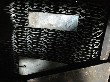
The two photos above are from TA0655 (top) and TA2190. The fin-design is the same on both radiators and also matches the radiator photo in the Service Parts List. The radiator is still in TA0655. The core was replaced (reusing the top and bottom tanks) on TA2190 in 2006 and the original core stored away. Tank Top Radiator Plates
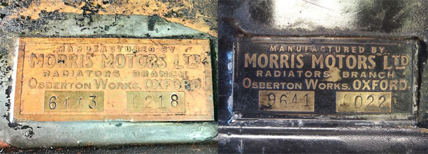
TA0655 left, and TA2190 right. These are the plates affixed to the top tank of the radiators. At first glance both appear to be the same but (Not that it matters!) they're not identical. Their type faces are ever so slightly different. We know these, or VERY similar plates were also used on earlier pre-war Morris and M.G. cars as well. The reproductions I've seen are similar but not quite the same design. If your radiator has these and you are having it re-cored (keeping your top and bottom tanks) be sure to point out to the firm doing the work that you don't want to loose them. They're soldered on and in heating the tanks to un-solder the core these will fall off and likely end up in their water-testing tanks. Fortunately we found them, but this happened with mine!
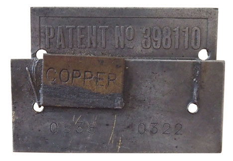
Lower, on the Off side rear of the radiator, are Patent plates and a ‘date of manufacture’ plate. On David Irwin’s early TA (see above) the Patent plate is separate and above the ‘date’ plate and appears to have a ‘tab’ on the sides for securing to the fins.
On TA2190 these plates were all soldered together then wired through the fins, solder being used again to secure the wires to the plates. I’ve read that the numbers on the left side of the ‘date’ plate indicate week and year the radiator was manufactured and those on the right are the serial number of the core. The small plate labeled “COPPER” would indicate the core material of the radiator while the header and lower tanks were made from brass. TA2190 has a production date of 07-Mar-1938 and its radiator plate indicates it was produced in the 8th week (toward the end of Feb) of 1938 thus about two weeks prior to the car’s production date. Thermostat By-Pass Hose Clip
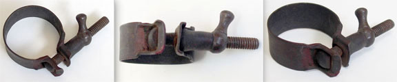
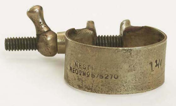
According to the Service Parts List there were 3 different sizes for clips of this design. Notice the one fitted to the by-pass hose on TA0655 in the photo above. The manufacturer was Nesthill and with the exception of the screw it is all brass. These were used on the water inlet pipe and the thermostat by-pass hoses while Jubilee type clips were used on the larger hose fittings.
The image here is the same clip which has been cleaned. An Original Rexine Half Tonneau
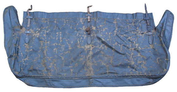
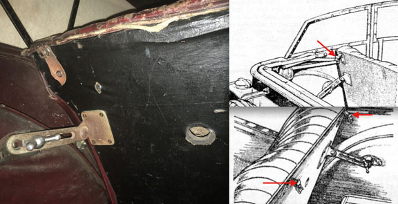
There can't be many of these left. Even though there are some replacement parts here and there most of this half tonneau is still intact. It fastened to the squab at three points. Below left shows the back of TA0655's squab with black Rexine and location of vent hole. The drawings, right, are from a contemporary automotive magazine in 1936 showing strap-loops which would have been original (red arrows) just behind the buckle.
Also note the black Rexine attached to the rear of the squab. It too is an original item. I believe that most current-day upholstry kits supply matching seat color for the rear of the squab. TA2190, a 1938 model, also had black Rexine there before being replaced. Did all TAs have 'black' Rexine here? TA Side Curtain Fixing Nuts
These had a stepped foot as above. An Early vs. Late Dipstick
On the left is the dipstick in TA0655. It matches the one in a photo of the early MPJG engine in the Owners Manual. The MG crested sticks followed but the Service List only carries one number. When did the change take place? Patent Plate & Tacks
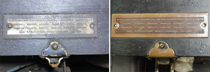
Patent Plates from TA0655 (left) and TA2190 While the copy on both plates remains the same, notice the 'silvered' portion has reversed. The type faces are also different. One of the more obscure items to be found on original cars are the small-head tacks used to attach the patent plate to the top of the tool box lid. The heads are smaller than the hole in the plate so were placed to the inside of the holes to 'bite' and secure the plate. The closing clasp-fixtures on the toolbox are brass and often seen polished on 'restored' cars but originally were painted black. Screw heads as well were painted black. The nuts (underneath) on all the lid screws were square, not hexagonal. In fact most, if not all, the smaller nuts (holding clips and brackets) on the front of the tub were square. Valve Clearance Instruction Plates
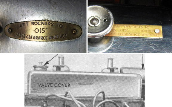
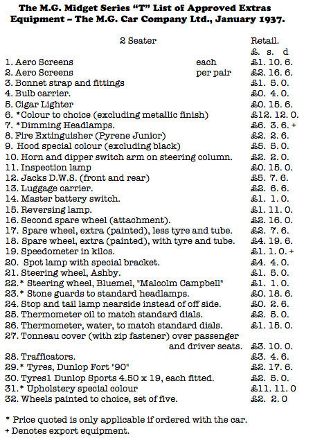
Different Rocker Setting Plates There were at least two different Valve Setting plates riveted to the valve cover. The first version was a brass oval that read .015” for setting both Intake and Exhaust. Later, at an unknown date, a rectangular brass plate replaced the oval and declared .010” Inlet and .015” Exhaust. The Service Parts List shows only one “instruction plate” (MG735/277) and the photo there (and in the Owner's Manual) shows this oval plate attached to the side of the valve cover. Although I’ve never seen one attached any where but the top there may be some very early engines with the plate on the side. The Works issued a Service Information Sheet in the summer of 1937 (actually directed at the VA but also relevant to the TA) recommending the valves be set to the .010” Inlet and .015” Exhaust numbers when hot ..same as the Service Data sheet (see Home page) by W.E. Blower. It is also interesting to read, in the April, 1938 reprinted version of the Instruction Manual for the TA Midget, the following with regard to setting the valves after a decoke of the head, pistons and block: “The engine can now be started and allowed to run at 1500 r.p.m. until the water rises to a temperature between70˚ and 80˚ C. Disregard the “.015” for all valves” and use the ten and fifteen thou settings. Or try setting them at .019” if you plan driving between 68 and 75 mph on your next road trip! Factory Optional Extras
This list shows us how many Extras one could get with a new car. The Carburetter Air Cleaner and Silencer
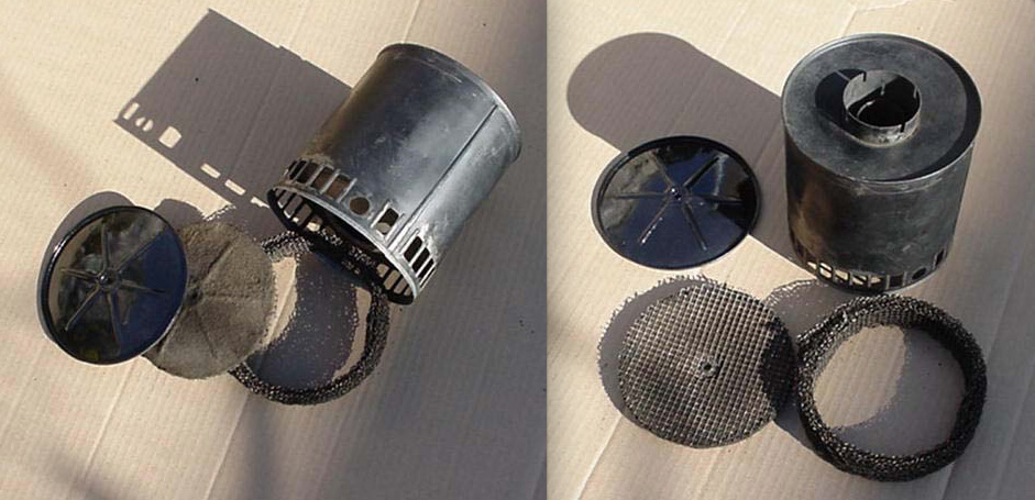
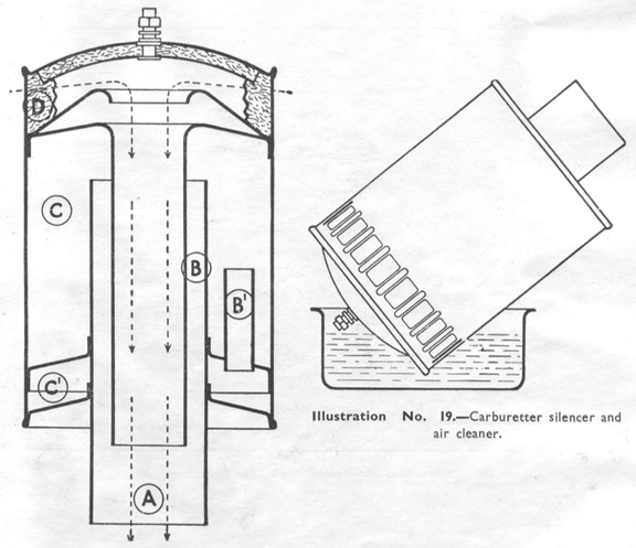
The large canister air filter on the TA serves two purposes. First it filters the air entering carburetors and secondly it was meant to 'silence' some of the noise of air entering the carbs on full throttle. This last point is best explained by the illustration and the words in the manual.
Illustration No. 19 From The Owner's Manual Cleaning and Re-oiling Although the end cap on my filter was not intended to be removed, I carefully lifted the crimped edge around the canister just enough to push it off in order to clean it out and to have a look inside. There are two 'elements' inside as can be seen in the photo. There's the wire mesh screen that fits around the inside of the canister and a felt disk at the end. The wire mesh is meant to be kept 'oiled' as per instructions above but I'm not sure what the function of the felt disc is unless perhaps as an aid in silencing. It actually does a fair job of filtering when kept serviced. And considering that all the Midgets before the TA had NO air filter at all it is a great improvement. There was no screw and nut at the center of mine although it appears a washer or something circular had at one time been snugged against the wire holding the disc to the end cap. On my car (as well as others have said) there isn't enough room between the tool box and the filter for anything like the nut and bolt arrangement shown in the drawing from the Manual. One intention for removing this end cap was in hope of taking out some of the dents. But since it is closed, with only a straight passage till near the carb end there's no way to get inside without major 'body work'. One owner who sent photos has a canister which on first sight is very close to the original in looks and dimensions. It is essentially a cylinder with ends which are connected by a long shaft running through the center and is threaded and captures the other end with a nut. It separates easily and he's using an MGB filter which fits perfectly inside. I wonder if there were more than one type of filter/canister used with these cars. Original canisters are not easy to come by, however a very close match was recently sold on eBay which had been removed from an Austin 18/6 (1937-'39) ambulance. Reproductions are of course being sold but aren't exact replicas. Hopefully More Will Be Added As We Go |