
The electrics in the TA/TB are unique to other T series cars. Its Headlamps, Ignition switch, Dynamo and Voltage Regulator/Cutout being the main differences. (TA & TB electrical circuits are almost identical.) The Headlamps, on early cars for sure, and perhaps the late ones as well the TB, had a solenoid operated reflector in the Near Side (Left Hand) headlamp which, when Low beam was selected, 'dipped' the reflector pointing the beam toward the ground while simultaneously dousing the Off Side (Right Hand) lamp so as not to 'dazzle' or blind oncoming traffic. This single lamp dipping arrangement was used for headlamps on Home market and cars shipped to France but for TAs destined for other countries the use of a second dipping reflector was standard. Likewise, cars headed to the Continent for instance might also have speedometers which read in KPH instead of MPH. Interestingly, the Blower Workshop Manual shows a wiring diagram for the TB in which the Near Side light is completely extinguished when Dipping is selected with no indication of a solenoid dipping mechanism. Although the focus was 'fixed' on the headlamps as they left the Works if one replaced a bulb with other than Lucas there might be the need to re-focus them. This, according to the Owner's Manual, was accomplished by moving the bulb "backwards or forwards along the axis of the reflector until the best lighting is obtained". Most TA owners today have changed to either sealed beam headlights or eliminated the dipping lens in favor of double filament replacement-type bulbs. Both methods give superior lighting than the original design. Use caution when replacing lamps which draw more current than was originally intended else the dynamo just won't be able to keep up. It should also be mentioned here that many owners have replaced the filament type bulbs in Tail and Stop Lights with LEDs which are far brighter, safer and offer much greater visibility in both day and nighttime driving. The use and conversion of LEDs should actually be another section that will be taken up later. (Be aware that LEDs are polarity sensitive. Most common LEDs are Negative earth and not suitable for the Positive earth TA.) |
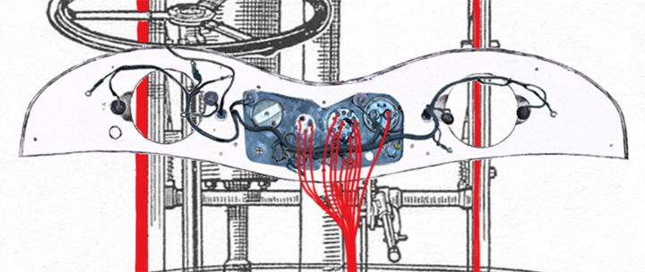
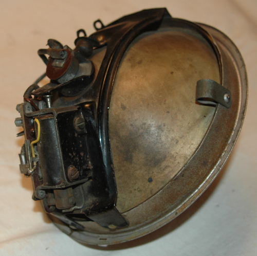
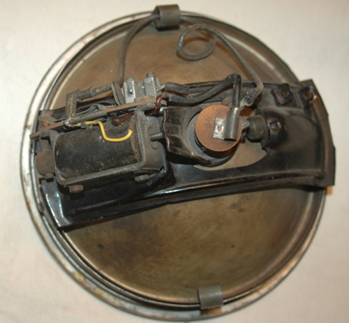
Solenoid Operated Dipping Reflector
The reflector pivots vertically within the headlamp bucket pointing (dipping) the beam lower, toward the ground.
There's a nice article on the dipping solenoids at Austin 7 dot org's site located here. Included at the site are schematics on the solenoid (which physically appears to be the same used on the TA) with an interesting explanation of their workings and some good advice if you're troubleshooting or restoring one. Remember that the Austin 7 used a 6 volt electrical system, however, not 12 volts as is used on the TA!
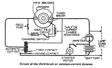
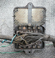
THE BATTERY CHARGING SYSTEMThere are few components that make up the charging system on the TA. There's a dynamo (generator), a switch allowing the choice of three amperages passing from the dynamo to the battery. (Summer, Winter and full charge when the headlights are on) And between the dynamo and battery there's a cutout which 'cuts out' the circuit between the two when voltage drops below a set level.
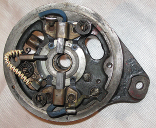
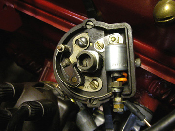
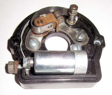
Dynamo/Generator The photo above shows the end plate of a TA dynamo with the three brush set up. The carrier for the smaller (3rd) brush is attached to a circular ring which is movable around the center of the plate. Movement of the plate, one way or the other, changes the amount of current (Amperage) the dynamo is putting out.
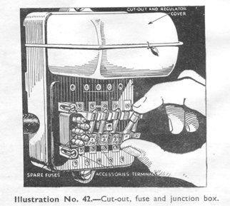
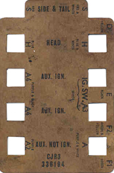
CJR3 Cutout Usually with 'regulated voltage' charging systems the state of the battery determines the amount of voltage supplied by the dynamo/generator. This is not the case with the TA/TB charging system. Here the dynamo output is constant. It uses a CJR3 cutout with two additional resistances inserted in the circuit in conjunction with the PLC switch to select a voltage which is then sent to the battery. CJR3 Terminus Guide A cardboard/paper guide such as the one above is usually found underneath the wiring hook-ups on the back side of the CJR3 Cutout. It helps to simplify harness hookups from the dash and other points to the fused terminals on the front. I would presume these to have originally been placed on all TA CJR3 cutouts. I found mine quite oily after 68 years in the engine compartment but it cleaned up enough to read the printing.
Lucas PLC High/Low Charge and Lamps Switch In the Low (Summer) position there are two additional resistances in the CJR3 cutout for the field circuit. When switched to High (Winter position) there is only one additional resistance in the field and selecting it sends a greater amount of charge (amps) to the battery. The greatest amount of charge is needed when the headlamps are used and swinging the lever to Head sends the maximum amperage the dynamo is capable of creating into the charging circuit. That rate is determined by the placement of the adjustable third brush in the dynamo.
The diagram above illustrates how the switch works (looking at it from the back). The ignition On/Off contacts are in the center while the outer connections are for lamps and charging circuits. And the illustration below might help understand the circuit using a CJR3 cutout and 3 brush dynamo.
CJR3 To RF95 Conversion
Converting A 3 Brush Generator To 2 Brushes THE THIRTY LIGHT
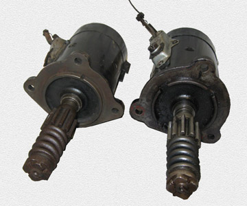
A green-lensed Thirty-Light is also incorporated in the electrical system being activated by a brass or copper contact inside the speedometer. These were also used in the TB and into early production of the TC. The reason for the Thirty-Light was to warn drivers that they were approaching the maximum speed limit enforced in many towns and cities throughout Britain in the pre war years. While it is interesting and amusing to watch it come on at about 20 mph and go off just over 30 a few modern-day TA owners have removed the wire leading to the speedometer and rewired the light for use as a Turn Signal indicator. THE STARTER MOTOR
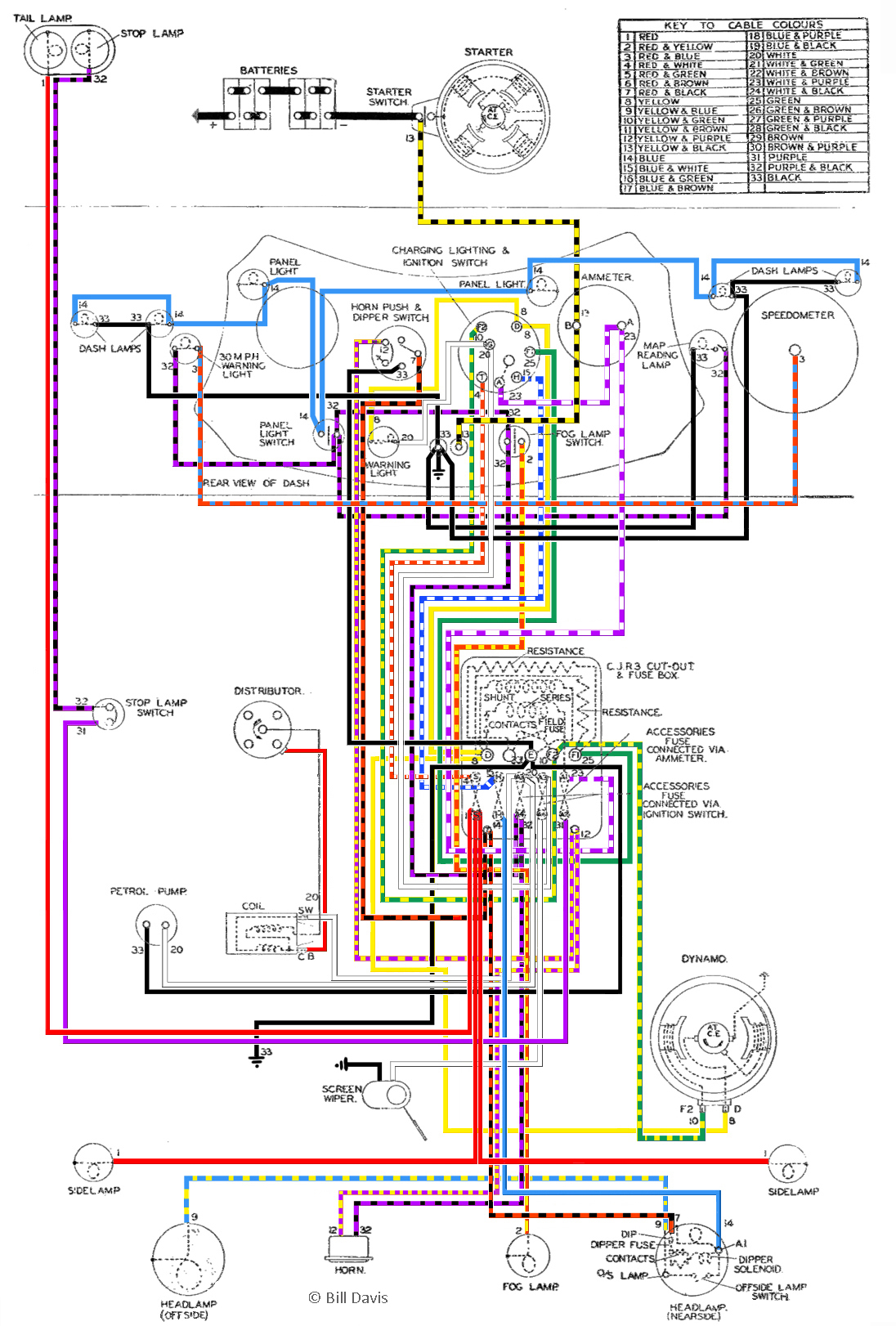
The correct starter motor for the TA was a Lucas M418A A84 with the cable operated solenoid mounted on the side as shown in the examples above. A MODIFICATION ORIGINAL WIRING DIAGRAM
From the Blower Workshop Manual This diagram above follows the correct color code for Home models with one dipping headlight. Click the image to view it larger.
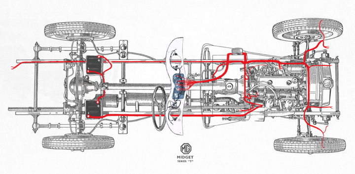
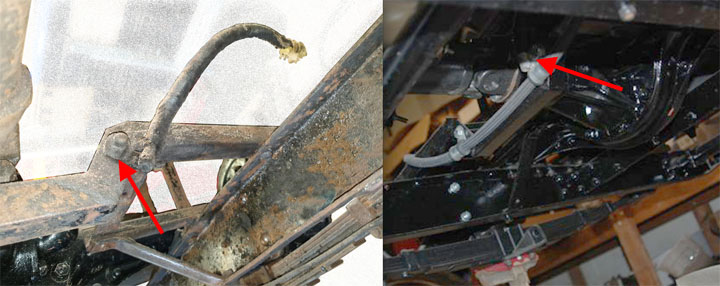
The TA Wiring Harness / Routing There has been some controversy over the route that the Battery-To-Battery cable originally took. Some owners, having two 6V batteries, have taken the cable over the top of the prop/drive shaft as did the MGA and MGB. However there is strong evidence that it went underneath the prop shaft and attached to the chassis with P-clips.
There is at least one factory photo of a TA chassis, without the body tub but with batteries in place, where the connecting cable takes the lower route. In the photo (above left) the short Positive Earth cable is still attached to this chassis. I also have another photo of an unrestored chassis which still has both the longer, battery-to-battery cable and this Pos. Earth cable still attached. The photo above (right) is the route used by a well known pre-war MG restoration firm for their TA/TB Tickfords. Notice the two P-clips retaining the connector cable.
Dash Wiring TA wiring is rather simple and available with original design cloth wrapping from several sources in the States, UK and Australia. One can also DIY your own but be prepared to spend a bit of time. A number of us have converted a TC harness for our TAs and most will tell you that it's easier and perhaps cheaper to have one made. I happened to have a Moss TC harness left after selling a car and decided to try it. It also included wires for turn signals which I wanted. The color codes are pretty much standard for British auto wiring and essentially the same between TA and TC. The big difference is that the Control box (TA) and Voltage Regulator (TC) are on different sides of the cars else it might have been usable as it was.. but no. After removing the original TA harness I labeled and measured the various groups of wires then unwrapped the TC harness and laid them out so as to match the needed TA lengths. Gathering them into groups, like a tree trunk with branches at the proper length, I reused the plastic non-sticky tape from the TC to form the basic harness. Once all the 'branches' were snuggly covered with the plastic tape I used black basting tape from a sewing shop and wrapped the harness again covering the plastic for a nicer look. There were a couple of difference I noticed in the new TC harness vs. the old original wiring. One was that the new, individual, wires didn't seem as thick, not as heavy gauge as the old, and that the new wire is plastic/vinyl coated (with color codes) where the old was rubber(?) then cloth covered. The cloth cover having the color code. I was concerned at first with the new wires seeming a lighter gauge (and there's not a lot of difference) but part of that may be in the rubber/cloth covering of the old stuff and also figure if they work for a TC then...! It sounds quick and simple here but it took quite a lot of time measuring, remeasuring and confirming the codes before I was confident I had it right. I did not replace the small original Dash Wiring Harness as it was in good enough condition to reuse. For a hybrid TA wiring diagram using an RF95 Control Box and two-brush dynamo, double filament headlights, turn indicators and other accessories see Ian Linton's rendition here. Interesting reading and a comprehensive article on a number of electrical modifications he made when he restored TA3120. Bob Butson has also written a very informative article on his use of LEDs when restoring TA0844. Once again, John James' online magazine, Totally T-Type 2 comes to our rescue. Read Bob's article here.
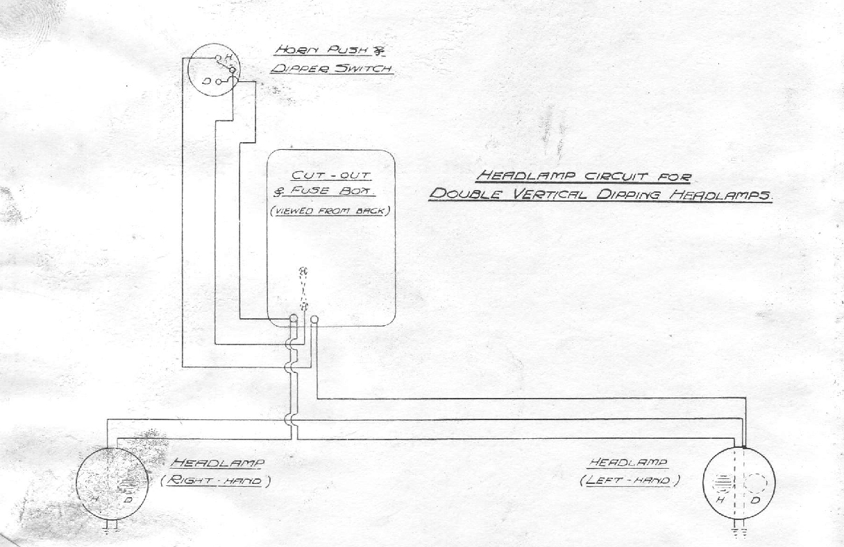
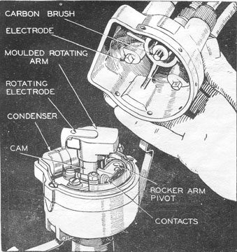
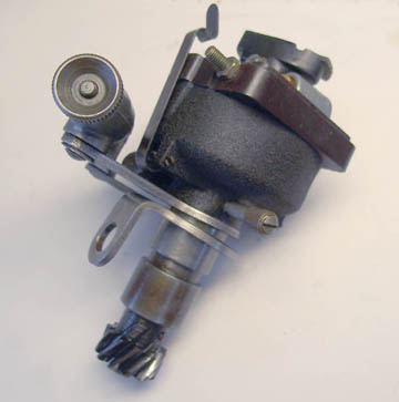
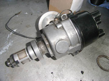
Here's the circuit diagram from the TA Owners Manual showing the route taken when wiring double filament headlamps. The connections are made on either side of the Headlight Fuse. Click the image to view larger. THE TA DISTRIBUTORA Lucas DK4A distributor came as original equipment on our cars. It uses a micro-adjustor underneath to fine tune the timing.
The distributor with cover removed - Instructions From The Workshop Manual -
Using The Micro-Adjuster Electronic Ignition Capacitor/Condenser ExchangeSeveral T series owners have reported capacitor/condenser failure in recent years. As our cars get older it’s not unusual to have the original capacitors begin to break down and need replacing but an alarming number of new capacitors fail right out of the box or in a very short time. Good reason to keep a spare in the tool box. The Distributor Doctor in UK is said to have very good quality capacitors and also sells Red Rotors. Their ‘Red’ rotor buttons are an improved version to the newer ones being sold which use a rivet to hold the contact on. Below is an example of a NOS Lucas capacitor (originally intended for an MGB or Midget) which has been hidden inside the distributor cap replacing the long original-type.
As can be seen in the photo a metal 'bridge' had to be added for making the contact at the rear of the newer capacitor with the base of the distributor. The pig-tail at the front required another screw and nut. When mounting a modern capacitor/condenser inside the distributor using extra screws and nuts as shown here make sure they're tight! Although the engine might stop before damage inside took place (if a screw came loose) still, you don't want that gamble. And remember, they do not have to be mounted inside the distributor to work. Another Approach
You can read more detail about this and his description of a quick and safe way to remove/replace your distributor in Issue 14 of the Totally T-Type2 found here. A VACUUM ADVANCE FOR THE TA There's a very interesting article here written by David Heath in Issue 34 of TTT2 explaining how he modified a Lucas 59D4 distributor for use in his TA.
The 59D4 is a vacuum advance type distributor as found on a number of Metro and Minis and once reconfigured for a TA requires a considerable amount testing before turning loose on an MPJG engine. I corresponded with David looking for more information about modifying a 59D4 distributor for my own use. He generously offered help and advice with various issues I had as the project progressed. After acquiring a distributor I modified the mechanical advance and also replaced the drive gear on the shaft. These gears are now available new from the Distributor Doctor in UK. He can also supply (or they can be sourced online) a set of assorted Lucas springs needed for tweaking the advance curve in the final stages of development.
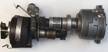
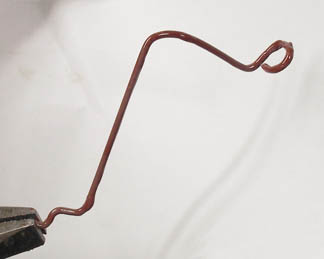
59D4 with DK4A Drive Gear Installed (vacuum unit removed) I made all the mods to the distributor, made a bracket to hold it securely in the block and even modified a spare intake manifold to accept the vacuum line. I ran it for a couple of hundred miles in mechanical-advance-only configuration and at that point my curves were good enough to try out the vacuum advancing but would still require a considerable amount of time selecting the correct set of springs so as not to burn holes in pistons. This is best done, as David explains, on a 'rolling road' where the car is stationary and mechanical adjustments such as springs on the weights, carburettor needles and even octane ratings can be tested easily without starts, stops and working along the roadside. Without a proper rolling road I got cold feet and went no further than an initial test to see that the vacuum advance was indeed working. But I can say this for the 59D4, it is a very good distributor! It was a very interesting project that I'd recommend for anyone wishing to learn more about timing advance curves and the workings of a distributor whether you follow through to a fully working vacuum advance distributor or not. And because a good used 59D4 is far less expensive than replacing a 'proper' DK4A with a little work you'll have a dependable and very serviceable spare. BETTER TIMING MARKS One of the essential needs in setting up the vacuum advance distributor is a reliable means of viewing Top Dead Center during dynamic timing. The factory markings on the crank pulley and timing chain cover are about worthless unless you have the radiator off. I'm sure this has been a sore point for lots of us wanting to use a strobe light for dynamic timing. And in fact it's impossible without adding marks of some kind. One owner I spoke with told me that he had used a wire marker attached to one of the engine strap bolts then painted degree marks on the pulley. Another suggested putting marks to represent TDC on the pulley and timing case housing over on the left side of the engine.
I used a heavy wire (clothes hanger!) and attached it underneath one of the bolts securing the timing chain cover. My greatest concern was that it might not be stable, would vibrate, and not allow an accurate reading with the strobe but was pleased (maybe even a little surprised) when it remained steady with varying engine speeds.
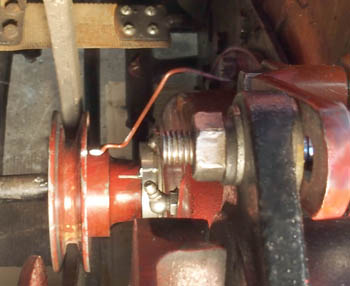
Timing Marks The photo above was taken before adding two more white marks (at 5 and 10 degrees BTDC) on the pulley near the wire marker. Notice the white mark at the back of the pulley. This photo is a little confusing because that large nut is holding the dynamo to the upper mounting bracket. In the photo it looks like there are 3 lines. (That short vertical portion is actually on the front of the seal housing.) If it could be viewed from directly overhead that line at the back of the pulley would line up perfectly with the white line on the top of the crankshaft seal housing. This is a good example of what you are faced with when trying to view TDC from the side of an MPJG engine. And the reason for creating better marks for dynamic timing. |
Contents of this Web Site are copyright © 2020
B Davis.