The MG TA Differential

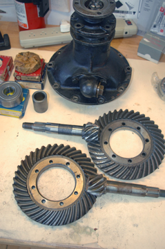
The TA has a conventional rear axle with power supplied from the drive shaft to the Pinion which turns the Crown Wheel, which drives the spider gears, which turn the half shafts. Simple enough.

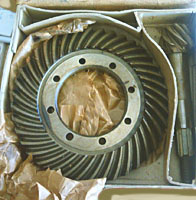
The Crown Wheel & Pinion are where the final drive ratio is determined. Originally this ratio was 4.875 to 1, in other words for every rotation of the rear wheel the drive shaft has to make almost 5 rotations. 4.875 to be exact. It's also known as an 8/39 diff. The Pinion having 8 teeth and the Crown Wheel 39.

Other ratios can be, and were, used in the early days especially for Trials cars. By replacing the original with a lower ratio (a higher decimal number!) more torque would be delivered to the rear axle giving it an advantage over the 8/39 when climbing a hill. The trade-off however is that the engine spins much faster at road speed and can not achieve as great a top speed as with the the original ratio.

It's good to keep in mind that "sports cars" of this type and of this era were just that. Sports Cars! They were not coddled or hauled to and from an event in an enclosed trailer in search of cups and trophies. The awards they won were earned by virtue of their abilities and reliability most often under rather harsh conditions. And while there are still, relatively speaking, several TAs (and other prewar MGs) on the road, very few are actively campaigned with the same vigor and enthusiasm that they were in the mid-late 1930s when they were 'new'. Today, with better road conditions and higher speed traffic the focus for many of us is trying to squeeze out a few more miles per hour and at the same time reduce our MPJG's revs per minute. And doing so without putting undue stress on the engine or sacrificing its reliability.

Since these gear sets can be exchanged with relative ease some owners increase the ratio giving a higher (theoretical) top speed but more importantly this decreases the rpms that the engine has to make to deliver a higher miles per hour. For that reason our 4.875 TA differential is highly favored by TC owners who seek 'longer legs' than the 5.12 to 1 gearing which came standard on their cars.

Although the CW&P exchange is the simplest way to change ratios, some have used complete differentials (sometimes called pumpkins) from other make and models of cars. While they may line up with the axle half shafts in the diff casing, they will have to have their matting surfaces machined to match the standard TA axle housing. Axle half shaft splines may also differ and have to be replaced. Although this is a much more complicated approach the primary advantage is that a greater selection of ratios are available when going that route.


8/37 - A HIGHER RATIO FOR THE TA

The TA Workshop Manual states that in top gear the standard 8/39 (4.875:1) differential delivers 16.67 miles per hour per 1000 rpm. Also bear in mind that when new top speed for a TA was "77 to 80" mph (4,619 rpm to 4,799 rpm). So where does this (and a higher ratio) fit in the real world?

Sometime back I asked several TA owners what they felt was a Safe Maximum RPM/Speed for their car. Of those who replied (I believe) all were running a standard ratio differential and 4.50x19 tyres. For one owner 3,000 rpm (50 mph) was a maximum while another said he "very rarely" exceeds 4,000 rpm (66.68 mph). Most said their 'cruising' speed was between 55 and 60 mph (3,300 to 3,600 rpm). Thus the majority of that small study felt 3,500 rpm (58 mph) with occasional bursts higher would be the answer. But almost to a man, everyone said that at 50 mph (3,000 rpm) their engine was happy and felt at that speed it would run forever. And even though Blower lists our Brake Horsepower to be 50 at 4500 RPM few now days seem willing to push their engine into that range. So to gain a few miles per hour without stressing the engine a CW&P change is in order.

The 8/37 (4.625:1) CW&P set is the simplest solution and is available from several sources in both UK and Stateside. These gears are a direct replacement for the standard set and will drop engine speed from 3,000 to slightly more than 2,800 rpm when traveling 50 mph. This is about a 5.4% increase in miles per hour per 1,000 rpm over the 8/39 gear set and theoretically works out to be almost 53 mph @ 3,000 rpm;
about 61 mph @ 3,500 rpm
and almost 70 mph @ 4,000 rpm.
An MPJG in relatively good health can easily handle this ratio.


SETTING IT UP

Setting up a differential is not a simple matter of removing one CW&P and bolting in another and might best be a job handed off to a professional. However with LOTS of patients and a few good measuring instruments it can be done by an average bloke if he's very careful. First off, much credit has to be given to Roger Furneaux (in Olde England) who has written an excellent guide which when carefully followed will take you through the steps necessary in building or re-building the T-ABC Type differential. He will also happily rebuild your differential if you'd feel more comfortable having an expert do the work. And while Roger's business is in UK there are willing experts on the west side of the Atlantic as well.

Roger's Instruction Booklet

Success in building a diff comes with the precise adjustments made to achieve the proper alignment of the two gears. The Crown Wheel being adjusted laterally across the axle while the Pinion's movement is adjusted fore and aft by the use of shims. Properly positioned they will have the correct mesh and backlash ..else bad/expensive things will happen back there.

A Destroyed Crown Wheel & Pinion

One of the more likely reasons for the damages shown here is Pinion bearing failure. Originally the front bearing on the Pinion was a double-race ball set caged in brass (3MDJT25) and many a diff has been opened only to find the balls loose and fragments of its cage in the bottom of the axle housing. Dirt, entering through the front around the Pinion shaft or a lack of oil, allowing the brass cage to over-heat and disintegrate, may also have contributed to this failure. To combat dust or fine particles entering from this end new pinion housing caps are now being manufactured which incorporating modern seals. These are well worth considering and available from Roger Furneaux, From the Frame Up and perhaps Moss and other suppliers.

When considering a rebuild or replacement of the bearings in the differential the experts in our group strongly recommend tapered bearings for both the Crown Wheel carrier and Pinion shaft.

Bearings numbers are FAG or Timken Tapered Roller bearings:
Pinion front - 62 mm x25 mm x25.25mm thick- #32305
Pinion rear - 62mm x 25mm x 18.25 mm thick- #30305
Carrier - 72mm x35mm x 18.25 mm thick- #30207 ( 2 required )


Pinion Shims For Tapered Bearing

Shims like these are needed when converting to tapered bearings and are fitted above the large Pinion spacer, just before the outer bearing. Various thicknesses are needed because the tapered bearings aren't as thick as the original ball bearings and they also allow the fine adjustment needed to pre-load the bearings. These too can be sourced in UK from Roger or From The Frame Up in the USA.

One other important item to note when converting to tapered bearings is that the use of a thick, 0.050" shim (not shown) placed under the Pinion carrier will alleviate any machine work there.


Crown Wheel & Pinion Mesh

Machinist's Prussian Blue is often used to determine where the gears mesh but Cadmium Yellow worked for me. I'm getting fairly close here in my early adjustment of the Pinion.

While Roger Furneaux's booklet deals primarily with replacing the unit with tapered bearings the W.E. Blower Manual also gives specific instructions for building a differential using ball bearings.

Measuring Backlash

Backlash is the amount of fore and aft movement that the Crown Wheel can make when the Pinion is locked in position. It is adjusted and set with the large Bearing Adjusting Nuts on either side of the Crown Wheel. Because this is a complicated process I make no attempt here to give specific instructions.
Correctly set however the backlash will be between 5 and 7.5 thou.


Axles ready to be reinserted into the diff

I didn't log the hours I worked at setting up my differential (actually I was building two at the same time) but I can say that it isn't likely to be a one-day job for an average backyard mechanic doing it for the first time. But by taking your time, being patient and double (or triple) checking your measurements, it can be done and makes for a very satisfying, rewarding job.

Now, by all means, make it a habit to....
! Check Your Fluid Level !
...and you might also invest in one of Roger Furneaux's magnetic drain plugs.


And as a final note:

There is one other fudge to gain a slightly higher final ratio. The use of 500x19 inch tires. I measured the circumferences of two inflated tires, off the car, and got; 450x19 = 91 inches; 500x19 = 93 inches. The 500 was a 2% increase in circumference which would add roughly 0.360 miles per hour per 1000 rpm to your ratio... whichever gear set you use.


| Home | Rebuild | Phoenix | Phoenix 2 | Phoenix 3 | Oil Filter | Tranny | Clutch/Flywheel | Electrical | Fuel Delivery | Misc. TA | Printed Materials | Originality |


Contents of this Website are copyright © 2020
B Davis.