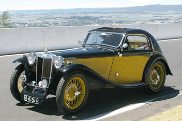
The TA has a 'wet clutch' meaning that it runs in oil. Engine oil. The oil is fed into the clutch housing through a hole in the rear of the crankshaft then slung onto the cork plate. Excess oil leaves the clutch plate cover through screens (designed to trap cork fragments). As it collects in the bottom of the flywheel housing it's picked up by the teeth of the ring gear and slung into a 'trough' on the left hand side of the flywheel housing where it drains back into the sump beginning the cycle once again. This archaic little trough can be seen at the 10:00 o'clock position in the photo further down the page showing the clutch, flywheel and rear of engine. The clutch itself has a double row of holes drilled through the plate, filled with 46 corks, and a spring center with splines for driving the first motion shaft. Between the cover and pressure plate are 12 strong coil springs. When engaged, the oily corks are sandwiched tightly between the pressure plate and the flywheel and in turn drive the transmission.
(For information on a Kevlar faced clutch see further down on the page.)
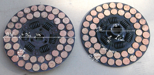
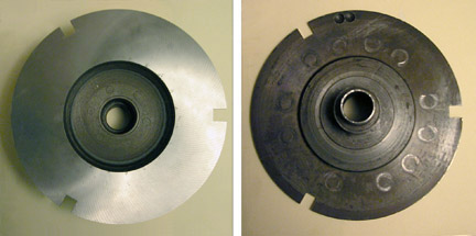
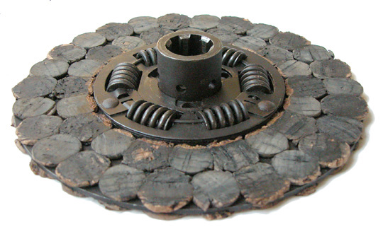
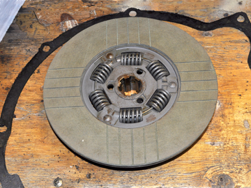
Front and back of a newly corked clutch plate.
Alan Webster, UK, sent this example of his clutch re-corked by Cantrill. The metal plate is 1/8 inch thick and the cork stands 1/8 inch proud of each side giving a 'new' clutch a total thickness of 0.375 inches.
Pressure Plate
The pressure plate above has been resurfaced (left) where it comes in contact with the corks. The three notches cut out of the plate correspond with square posts in the flywheel assuring that the plate is locked together with the flywheel. The rear of the plate shows wear marks from the springs.
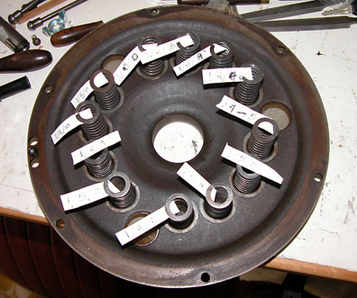
The Pressure Plate Cover
The pressure plate was removed from the cover, above, in order to resurface it and to check the springs. While apart I weighed each of the springs then placed them around cover in a manner to best balance them within the cover. The cover with springs, pressure plate and throw-out bearing attached can then be mounted to the flywheel (less the cork plate) and sent out for balancing as a unit.
Transmission attaches to bell housing #8. Engine to flywheel housing #7.
While researching cork clutches with the intent of re-corking it myself I found the following information that Mr. Brian Jackson of Australia had submitted to a Morris forum:
"The corks should firstly be of top quality, from a wine bottler for example, with no rubber or synthetics.
They are normally cut to about 3/8" placed in boiling water to soften them and inserted with equal amount each side of the plate. They are then finished by grinding or sanding until flat, within 0.010", across all corks and measure 5/32" or 0.156" each side and before the cork is compressed.
One way to sand them flat is to make a wooden disc the same diameter as a sanding disc, put a bolt or mandrel through the centre, glue a sanding disc to the wooden disc and place in a pedestal or bench drill and with the plate supported dead level with the table of the drill move the table slowly up to the disc and sand the corks, turn over and repeat for the other side."
I corresponded with Brian, a pre-war Morris owner, looking for information and comparing our cars and the similarities in the wet clutch and flywheel they share. In one of his notes he sent copies of Morris factory Service Information sheets from April, 1938 for a Morris 10-CWT. VAN which I found very useful. There were photos, and drawings describing the unit and the method used to disassemble/reassemble it. The major difference between the clutch/flywheel unit in the Morris Van and the TA is in the mechanism that operates the clutch. I've re-created the drawing (above) and made the changes to show it as a TA unit.
Thanks, Brian !
Mating the transmission/bell housing to the engine
There’s been only one mention about how to join the transmission with the engine. That was briefly on the Rebuild page but this needs more explanation as it is very easy to go wrong here.
First thing is to remember that the clutch release on the TA works in the opposite direction to other cars. When the clutch is depressed on most cars, a force (usually in the form of a carbon TO bearing) is pushing fingers in the pressure plate toward the engine causing the release of the driven plate.
Not so with the TA’s wet clutch arrangement. The TA uses a ball race Throw Out/Withdrawal bearing. And when the clutch is depressed a fork which is in front of the bearing pulls the ball bearing (along with the pressure plate) toward the rear of the car thus releasing the driven plate. This unique arrangement achieves the same result but causes some confusion when reconnecting the transmission/bell housing to the engine.
Understanding The Mechanism
The image below shows the movement of the Throw Out bearing. On the left the clutch would be engaged. With the fork pulling it rearwards (on the right) it disengages the cork plate.
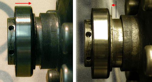
Care must be taken to raise the fork so that it rides up and over the Throw Out/Withdrawl bearing as these units come together. If you don't get the fork in front of the clutch withdrawal bearing when you bolt up the bell housing to the engine you will crack the bell housing before the gap is closed!
Note the drawing below.
On reassembly: The shaft (12) operating the fork (9) MUST be rotated counterclockwise so that the fork can go up and over the TO bearing (18) as they are mated together. Notice the rounded ’fingers’ on that fork face the rear of the car and these fingers, working against the TO bearing, are what ‘pulls’ the pressure plate (32) into the pressure plate cover (26) disengaging the cork plate.
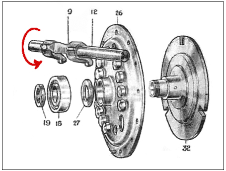
One other note here; the TO bearing is directional.
Meaning that the thrust side of the bearing faces forward towards the clutch plate. The fingers of the fork act upon this surface. If placed with the balls toward the clutch plate (and all else is assembled correctly) when the clutch peddle is depressed it will separate the bearing and you’ll have loose balls all inside the bell housing!
It may be mentioned elsewhere but because this arrangement of pulling the clutch toward the rear puts a strain on the engine mounts there’s a need to counter it. This is accomplished by tension of the two webbed straps attached to the front engine mount and the cross brace on the chassis under the radiator.
TA Clutch with Pedal Return Spring
After some discussion on the T-ABC forum as to where the clutch pedal return spring was attached or for that matter if one even existed (some owners report having no spring at all on their car) I had another look at the Service Parts List and indeed there was a clutch pedal return spring. I have also revised the drawing here to more nearly represent the TA Bell and Flywheel Housings (#s 7 & 8) which had been Morris Van items in earlier editions of this page.
According to the TA Parts List, for early cars, there is a Clutch Pedal Return Spring (S73/7) and one Bracket (S44/68). For cars with chassis number TA2486 and later there are two brackets and the spring. “Second bracket (on clevis pin)” part number (S44/128)
I’ve found no information on where these “brackets” attach or what they look like so I’m making a ‘best guess’ here, as I too have no return spring on my car.
Item (51) in the illustration above might be an elongated washer replacing the large round washer at the bottom of the brake pedal where the Clevis Pin attaches the adjusting rod (43) to the pedal. Item (52) being the spring and item (53) being a bracket that ‘might’ be affixed to the lower Off Side bolt securing the Bell Housing (8) to the Flywheel housing (7).
These are guesses, of course, and I’d be pleased to revise the drawing or post a photo if someone can show us the actual brackets and their mounting points.
From the 1938 Morris 10-CWT. Service Information sheet
Access to clutch after removing gear box and clutch housing. To dismantle, undo flywheel bolts and remove complete pressure assembly. Driven plate held on three studs by single circlip. To dismantle pressure assembly, remove locking nut from hub, remove thrust race and separate pressure plate from cover plate. Two adjustments only for clutch. Screw adjustment at bottom of pedal to give 1in. free travel at top. Set travel stop so that pedal arm comes against it just as clutch stops spinning.
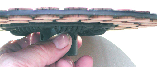
Ultimately I chose to have my clutch re-corked rather than the DIY method. I felt the price charged by Mr. Fellows in El Paso, TX was fair and was about the same as the UK prices. There is a difference, however, in the method used for getting the correct thickness between the UK services and that of Mr. Fellows. The corks are trimmed (or machined) to the correct height off the plate by the UK suppliers. Mr. Fellows, a 'Hudson man', uses compression and the heat of an oven to set the exact height. I questioned his method, since trimming was the only way I'd heard of at that point. He assured me that his Hudson cork clutches not only kept their set but as for strength were used in winning dragsters. When it was returned I was surprised to find the corks a dark color and oily and asked him why. It has to do with the solution of transmission fluid they are soaked in prior to going into the oven. There is another noticeable difference between his recorking and that used by the UK firms. Using his method there's more active surface area against the flywheel and pressure plate. This is visible by comparing the photo below with those at the top of the page. I do not know what significance the difference makes. However the corks on his clutch rebuild must be trimmed on the perimeter of the plate so the corks do not interfere with the three square 'pegs' in the flywheel as seen when installed in the lower photo. The corks on the photo below have not yet been trimmed.
Untrimmed Corks
The photo below is the clutch installed. It has a very smooth take-up and I've been pleased with it. And, having had a second look at it after 1600 miles (problems unrelated to the clutch), it looks very much as seen in the photo; showing little or no wear and still maintaining the dark color.
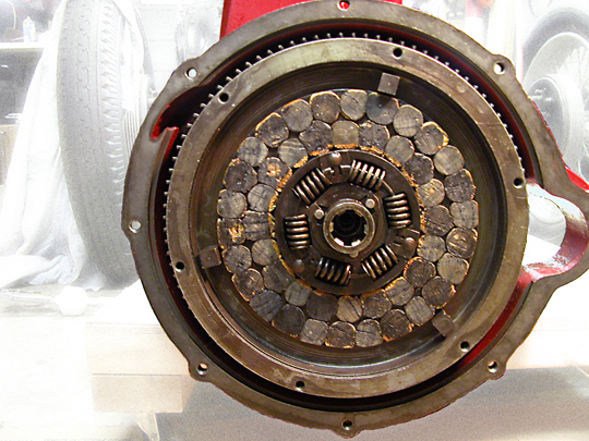
Ready For Pressure Plate and Clutch Cover
One thing that must be done before installing a new clutch (from any supplier or a DIY job) is to soak it in oil for at least 24 hours prior to assembly. I figure the longer the better and my clutch was bathed in oil for over a week before the original assembly took place.
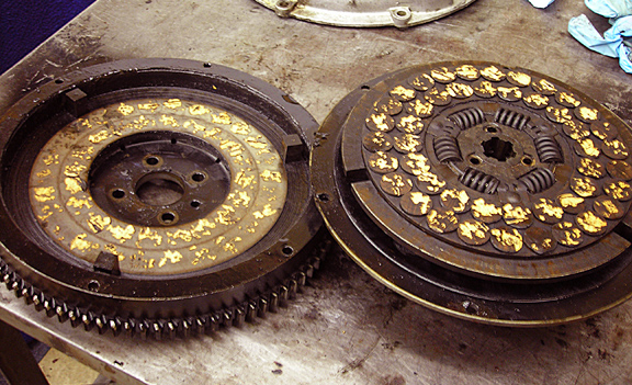
Corks Adhered To The Flywheel
The photo above shows the result of corks sticking to the flywheel. And they are stuck tight to the pressure plate as well! Considering thickness alone, the corks appear new and should have had plenty of life left in them. I can't say for sure what went wrong here but I expect this clutch had had very little use after being rebuilt. I've had my own clutch tend to stick when the car went undriven for extended periods of time. And I expect moisture was a large part of the problem, essentially by rusting the corks to the metal surfaces. I've seen on my flywheel and pressure plate where rust pitting occurred leaving the circular imprint of the corks. By its very nature, cork is likely to retain some moisture. And there's bound to be water vapor in a hot engine looking for a place to hide. Perhaps heating a new cork plate in an oven right before soaking it in oil would help but that's only a guess. However, both flywheel and pressure plate surfaces can be refaced to clean up most of the pitting. And what can be done to prevent the problem? I don't have the answer but, before reassembling the engine, would suggest following the time-honored rule of soaking the cork plate for a sensible amount of time in oil; don't assemble the pressure plate and cover to the flywheel then let it sit in the same position for a long time; get it into use as soon as possible and... drive the car!
Cork clutches can be rebuilt by:
Ron Fellows - El Paso, TX, USA
Charles Cantrill, Birmingham, UK
Paul Beck - Vintage Car Parts, UK
Kevlar Faced Clutches
Tony Slattery, former co-owner of TA 0355, describes the clutch that was replaced in 'Grace'.
On inspection of the clutch it was found that quite a few of the corks had completely disappeared and there wasn't much life left. The plate was sent away to have Kevlar fitted. And in accordance with the rebuilder's instructions it was soaked in oil for a few days. At first it was thought all had been for nothing, as the clutch was easy to slip. However I soon realized what was happening and all is good now! When you let out the clutch you have to pause momentarily until the oil is dispersed. If you ease off the power the clutch will bite and away you go. As the Kevlar has such a larger surface area, you can understand that it takes longer to squeeze out the oil (through the 'hatching') than from the ends of the corks – pretty simple.
Certainly uprated springs would have squeezed out more oil however that would have applied more load to disengage and I didn't want to risk possible damage to the bell housing which has to carry the additional load. So this is a downside of the kevlar, but you cannot burn it or wear it out like you can the cork clutch. The car was driven on some serious steep hills at the 2013 National Meeting, and there was no slip whatsoever.
TA 0355's Kevlar clutch
Lightening the Flywheel
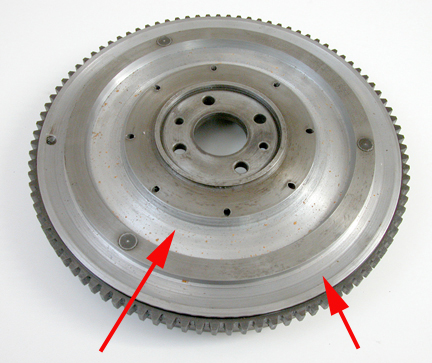
METAL REMOVED FROM THE SHINY AREAS
Lightening the flywheel to achieve a faster revving engine might be more beneficial to those using stock (non counterbalanced) crankshafts. There may be a slight trade off though as one of the features of the TA is the torque it delivers at lower speeds. And that is a direct result of the massive weight of the flywheel and driven plate as originally produced.
The TA flywheel is a hefty piece of metal! Before machining, mine weighed 31 pounds. By removing 4 and 1/2 pounds I've reduced the weight by almost 15%. It was removed from the front (the engine side) in the areas indicated by the red arrows. The machinist who did the work said that cutting it was difficult and slow going. He'd machined lots of flywheels but had never encountered metal with the characteristics in this one. Some of the area left uncut (between the three small dark circles) might also be machined away but those circles are actually pegs that anchor the square posts on the other side and probably should not be shortened by very much, if at all.
The advantages of taking weight off the flywheel will depend on the crank used. I can tell no difference in the rate of increase in RPMs by having lightened my flywheel. But that's because the balanced cranks are heavier and in my case by over ten pounds to that of the original. Therefore I've added five pounds total to the rotating mass!
The jury is still out regarding increased performance from having lightened the flywheel. Too much time had passed and too many factors were involved between the original running and the rebuild of a friend's engine to determine the difference in performance between original weight and his lightening it. And while keeping in mind that his is a non-counterbalanced crank he reports that it revs quite smartly, cruises nicely at 50-55 mph and doesn't believe lightening it has been of any harm.